Automation system for a serial micro CHP system*
The task
* The project was supported as joint research project and was financed by the Land Saxony-Anhalt and the EU.
Intelligent decentral solutions for power supply are increasingly important. An important block for a decentralized power and heat supply are gas-fired engine CHP systems in households and business enterprises, who brought some new models on the market during the past years.
The producers, who enter this techniques are facing a big challenge. Not only machine building, combustion-engine technique, acquisition and production have to be handled. Today CHP systems, like almost all products, contain a lot of intelligence in form of control hardware and software.
To be able to offer customers in power engineering a flexibly adjustable, but still reliable and quickly implementable solution, ProSign has developed the Imhotep platform. The power management components of the engineering office Stephan Widera are based on that.
The hardware is based on an embedded system with Intel Atom Processor and process specific interfaces, as f. e. temperature measurement, 3-phase power management and ignition-coil control. As OS, RTLinux was implemented, on which all in all five iCon-L kernels are running. You can find a description of the Imhotep platform here.
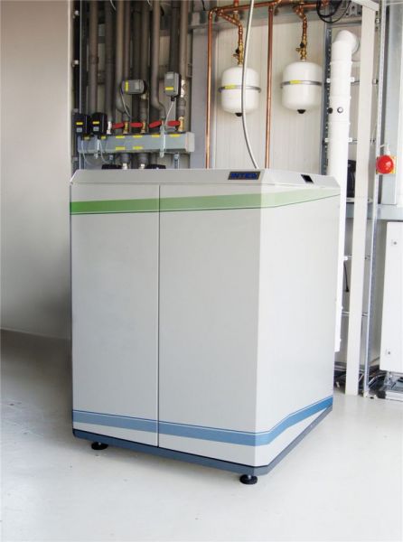
The home power station from the intelli production GmbH from Barleben, Germany, has developed an electric capacity of 2.6 kW and a thermal capacity of 6.5 kW. The single-cylinder engine is an in-house development and is designed for an especially low need for maintenance. Despite changing the ignition coil and oil, no wear parts have to be exchanged, which makes the operation especially economical.
In order for the micro CHP system to replace the gas holder in a single or multiple family house, a heat storage and an intelligent management are demanded. Only if the peaks in the heat load are temporally spread, a relatively small generating capacity can still guarantee a high coverage of heat load without the peak load boiler having to support too much.
Power management software components for iCon-L
The power management software is composed of hierarchically arranged iCon-L macros, the upper layers each represent different machine parts. This segmentation of single modules has the advantage that changes can be made in preferably few central changes, f. e. if a new heat generating module or a new interface for a machine part should be added.
In the next part, the software modules for the fully equipped system are introduced. The installer can deselect machine parts that are non-existent in online mode.
| Project | intelli Micro CHP system |
|---|---|
| Short description | Development and production of an automation system for the serial micro CHP (Combined Heat and Power) system for the company intelli. |
| Customer | Intelli production GmbH |
| Service provided by ProSign | Development of a complete automation platform for the micro CHP system - Adjust our programming system - Electronics development - Implementation of a real-time Linux kernel - implementation of an operating data acquisition system based on an SQL database - Remote maintenance system over VNC and SQL interface - grid and plant protection with diverse redundancy - motor management (ignition, performance control) |
| iCon-L version | 4.5 |
| Target systems | 5 independent software controls on an ATOM processor with specific RTLinux solution |
| Process data points | Approx. 40 data points are directly on the compact control and further I/O data points over CAN bus |
| Features | The project took over 3 years and for ProSign, it is the biggest project regarding its complexity. |
| Size of the application | 11,879 function blocks |
Engine CHP system
This component is the interface to the subordinate engine control, which was developed by intelli production and ProSign. On the one hand, the CHP component provides basic functions like keeping the minimum time, operation time and downtime, emission test operation or automatic restart attempts after a malfunction. On the other hand, this component provides the main basic data for the higher-level power management like f. e. electric/thermal power, start-up time or minimum and maximum temperature for flow and return.
When using another CHP system, only this CHP-specific component has to be rewritten. The engine CHP component provides new data and boundary conditions for the power management and can stay unchanged in general.
Peak load boiler
When controlling the peak load or backup boiler, the boiler with internal temperature control as well as boilers where the burner has to be controlled from an external control can be operated. Similarly to the CHP controlling, all subordinate functions (controlling, supervising, minimum operating time and downtime, emission test operation) are summarized in this model.
Buffer storage
The buffer storage module has the task to identify the status of the buffer storage as exact as possible.
- Identify the heat load in the storage, which is usable for the consumer.
- Identify the heat load that the CHP system can store in the storage, before the max. allowed return temperature is reached.
A special challenge is to work with as few as possible storage temperature sensors. Big CHP systems have at least ten sensors, which is impossible to implement in a micro CHP system because of the costs. In small CHP systems at least three sensors are implemented. To be able to change some switching points (f. e. recharge start when warm water is needed), the installation height of the sensors have to be changed at traditional control concepts. The once chosen installation height does only fit in one operation mode. This method is extremely inflexible and furthermore any changes are connected with a lot of on-site work.
That means that a target conflict arises between low costs for the sensors on the one hand and a high flexibility or remote maintenance on the other hand. An alternative could be the concept with five storage sensors combined with an intelligent measurement processing. With the measurements of those five sensors alone, the storage volume can be gathered in 20 % steps. In order for the fill level not to jump in big steps like that during loading and unloading the storage, an interpolation was additionally implemented between each step. This interpolation is based on the difference between produced and used power and makes sure the measurement process works steady, so the switching points for starting and stopping the CHP system and boiler can be chosen independently from the installation position of the sensors.
Only in this way a power management is possible, which can change switching points and can adjust to the daily need of the consumer.
Power management component
The power manager can work the CHP system and the boiler in one of four operation modes:
- CHP system off: The boiler takes over the supply
- CHP system heat operated: The CHP system takes over the heat demand with the highest amount possible
- CHP system heat operated with power priority: The CHP system is ran heat operated, the storage, however, will never be heated up to 100 %. The remaining backup is used to occasionally run the CHP system power operated, even though the heat demand is low at the time.
- CHP system power operated: The CHP operation will only be adjusted to the power demand, as long as the storage has not reached the maximum temperature.
The boiler always covers the difference between the thermal output of the CHP system and the heat demand of the consumer. During malfunction of the CHP system, it will automatically be switched to the boiler as heat source.
An important function of the power manager is the temporal coordination of producers and consumers. The controls for heat circuits and water heating are reporting estimations about when they will need how much heat. The power manager now temporally lines up the operating times of the consumers, so the CHP system can supply enough heat without having to use the peak load boiler. For this purpose, the heating processes of the building and the hot water storage is temporally stretched. Now the storage ability of the buffer storage, the hot water storage and the mass of the building is used.
The switching points to start or stop the CHP system depend on the storage fill level and are chosen in a way that the backup heat needed by the consumers stays in the storage. On the other hand, a preferably big storage volume can be used for extending the life time of the CHP system.
Controlling the heat circuit
The heat circuit automation does not only include the classic heat curve with reduced outside temperature and a time clock for the operating times. This software component is designed to interact with the power management and negotiates the assigned thermal heat with the power manager.
The heat circuit automation considers the thermal behavior of the building using a thermal building model. The model considers the heat loss through walls and windows as well as heat storage in the building mass and the heating surfaces. With this model, the dynamic heat demand of the building can be calculated, which, other than a static heating curve, also considers the additional need to heat up in the morning or after a hot water priority load.
The building model transfers to the power management how much power is needed in which period. From that, the buffer storage backup is calculated, which is necessary to bridge the power peak, if possible without using the peak load boiler. The power management sends back a power assignment which determines the heat output.
Especially important is an easy implementation and parametrization of the heat circuit. Complicated controls with many non-transparent parameters are usually not parametrized but kept as factory settings. Consequently, comfort and efficiency mostly leave much to be desired.
The parametrization was simplified radically, so this kind of problems will not arise for these complex building models. The installer only has to implement some machine data in online mode, which are easy to find out. The most important parameters are:
- The type of the heating surfaces (selection from radiator, convector, floor),
- Design temperatures, design heat output,
- Type of building (f. e. residential building, commercial building with assembling shop, big single-purpose building) and
- Insulation standard (f. e. old building, Heat Insulation Ordinance, passive house).
It is not necessary to calculate abstract numbers as f. e. the time constant of the building.
Controlling water heating
The software component for water heating can control the most systems relevant in the field:
- Combined storage, which is a drinking water bubble integrated in the buffer storage
- Drinking water storage with built-in loading heat exchanger
- Fresh water station, where the drinking water is heated with a heat exchanger after the continuous flow principle
Furthermore, the component includes an important side function as f. e. controlling a circulation pump, frost protection function and a thermal disinfection. In direction of the higher level power management, the main task of the hot water component is to request enough heating volume in the buffer storage, so the hot water comfort is ensured at the desired time.
Here, the main focus is on a preferably simple and for the user transparent parametrizing. The installer neither has to parametrize buffer storage temperatures, from which a recharge takes place, nor has to change the installation height of the storage sensors. After the type and volume of the water heating has been chosen from a catalogue, the desired Energy Efficiency Ratio (EER) of the machine will be implied as central parameter. The EER according to the standard DIN4708 roughly corresponds to the approx. number of average equipped apartments, which can be supplied by the machine. The necessary heat storage in the buffer storage and the switching points for starting the CHP system are calculated automatically in the EER.
The way to the tailored power management system
Each micro CHP system, which is new on the market, is unique and needs a customized power management software. The introduced individual component already covers a wide application field and can be adapted to many different values of cogeneration units, storing and heating circuits. Nevertheless, a customized implementation is always necessary, which should be drafted shortly below.
Configuration of the system
First, the system architecture of the power management application is developed according to the requirements. For example, the type and max. number of power producers and consumers is set. That makes especially sense for cascaded CHP systems or if CHP and heating controller should be marketed as separate devices.
Programming customized add-ons
After the basic frame is set, the application will be completed with the software components, which are specifically adjusted to the product. Included are f. e. the interface for engine control or special functions, which distinguish this product from competitors.
The biggest and most important task in this project phase is the common development of a user interface for the CHP automation. The Imhotep platform has a graphical user interface with a touchscreen to operate. The design of the interface does not only have great importance for ergonomics and therefore for the customer’s acceptance. The design and the operating philosophy are also key elements to shape a brand and are therefore always developed customer-specific and with close communication.
Simulation test
The thermal processes in a house power system as f. e. heating the building mass, have time constants in the range of hours up to some days. It would be very time-consuming and expensive to do the initial commissioning and debugging of the software directly on the “living object”. To work more productively, a simulation environment is available, which recreates the thermal behavior of all components. The power management software as well as the simulation environment are designed so the whole system can be simulated strongly accelerated in “quick motion” mode. In that way, debugging and a useful pre-configuration of all parameters are possible in a very short time, even before the software is running on the target hardware for the first time.
Test and parameter optimization at the machine test bed
A house power system always has to be checked as a whole on a test bed before it can be applied in a customer’s facility. A pure engine test bed, where only the functions of the CHP system are checked is not sufficient. To be able to evaluate the performance of the whole system, the CHP system has to be evaluated and additionally the interaction between peak load boiler, storage, consumer and control have to be observed.
The performance data and the utilization ratio (which not only includes the deficits in the CHP system, but also the storage deficits) have to be measured at the test bed under defined circumstances to reach the eligibility of a CHP system according to the German cogeneration law.
Another reason to conduct enough test beds is the verification of the performance data, which are ensured to the customer. On the test bed, f. e. specifically a hot water tap profile according to DIN4708 can be simulated when at the same time the heating energy demand for a winter’s day is ran. Only like that the hot water supply can always be assured. With realistic hot water tap profiles and heating loads, however, estimations about efficiency and optimization impacts of the facility can be made.
ProSign and the Engineering office Stephan Widera are offering all services that are necessary to test a house power system in the laboratory:
- Development of customized hydraulics concepts for one test bed
- Planning the whole test bed automation including building the electrical enclosure
- Designing an individual test bed software, which simulates the thermal and hydraulic behavior of the building (heating circuits/hot water consumption) and notes all measurement data
- Designing load profiles in which defined load scenarios for the heater and hot water are ran
- Designing an inspection plan, analysis of measurements and conclusion making about handling advices for the optimization of the system
Support during field testing
The next phase of market introduction after laboratory testing generally is field testing at pilot customers. A successful field test starts with selecting fitting field test objects. The objects should cover the planned range of application of the house power system as far as possible. On the other side, the number should be manageable to be able to look after the installations. Besides the type of field test object (size, type of building, usage, heating system etc.), further factors like f. e. approachability and accessibility for service employees, connectivity or the strategic meaning of the customer are to be considered.
During field testing and also in the serial product, all measurement data, error messages and diagnosis data in a SQL database are stored on the Imhotep control. Through an encoded internet connection, the iCon-L program as well as measurements can be accessed. Furthermore, a remote parametrization is possible for service employees via remote control.
Equipping the objects with additional measurement equipment is another point, which has to be planned carefully. For example, to issue an energy balance, the heat quantity in the installation has to be measured. As a matter of costs, the necessary sensors are mostly missing in the serial installation, that is why an installation of additional sensors is useful in field test objects. They can be connected to the control over a bus connection, so the data of the additional measurement equipment can be stored together with the operation data of the CHP system in the measurement database.
The next important step is the evaluation of the gathered data after a successful field test. The power management components receive very detailed diagnosis data, with which the behavior of the installation is reconstructable very accurately over months. Thereof, many important information can be gathered, which influence further development of the product up to the start of production:
- utilization ratio, losses, reasons for losses under real operating conditions
- applicability of certain installation components (f. e. storage in different sizes and design) for the usage in the house energy system
- statistic data of the CHP system under real conditions, f. e. the number of achieved start/stop cycles and operating hours
- Feedback from the users about the installation (f. e. felt comfort) and about operability of the control
If desired, all steps of the before outlined field test scenarios can be advised and supported by the engineering office Stephan Widera.