Connections
1 General
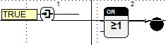
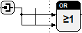
Connections serve to specify the data flow or the control flow between the blocks. Data flow-oriented programming facilitates the connection of one output with one or more inputs. In case of several inputs, branches occur that are marked by nodes on the connections. On the other hand, control flow programming facilitates the connection of several outputs with one input, e.g. in case of flow charts. Such branches create subconnections which can be edited separately.
Connections can be drawn in one worksheet window and, by means of input and output blocks, across several hierarchic levels.
Colors and types of lines are indicative of the type of connection as well as the data type used (refer to the Signals and Parameters section). Connections can be only drawn between compatible connectors.
The sections below describe the operations for drawing, deleting and selecting connections.
2 Draw connections
Connections can be drawn within one worksheet or across several hierarchic levels. The connection of free connectors in one worksheet is described first.
Procedure
1. Click a free connector by pressing the left mouse button
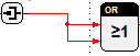
When the mouse is moved over the connector of a block with the smart pointer activated, it assumes the shape of a pen. If the left mouse button is pressed, the cursor is displayed as a reticle. When moving the mouse horizontally or vertically and clicking with the left button again on the free area, line segments are drawn and bend points are set.
2. Click another connector or a connection by pressing the left mouse button
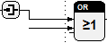
If a connection is permissible, a connection is created between the last bend point or the connector and the selected target point. If a directly horizontal or vertical connection is not possible, autorouting calculates a right-angled line path without passing through other blocks or connections. If autorouting is not able to create such connection, a diagonal line is drawn to directly connect the starting and the target points. Diagonal connections need to be orthogonalized first before they can be used in the same way as other connections.
Error messages are generated in case of inadmissible connections.
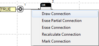
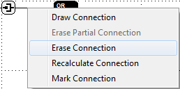
To generate branches, connections can also be started on the connecting lines. To this end, call the Draw Connection command in the context menu for lines. Thereafter, drawing of the connection can be continued as described above.
Connecting across hierarchic levels is facilitated by the input and output blocks of the Standard library. The following operations are required to connect, for instance, the output of one block with the input of another block located in a macro.
Procedure
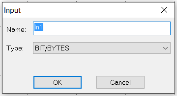
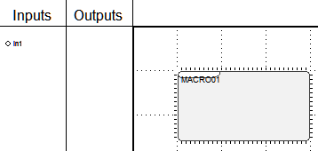
1. Insert an input block in the worksheet window of the macro
After the block has been inserted, a dialog opens where the designation and the data type can be set. The output type of the block outside the macro should be selected as a data type. The name of the input block must be unambiguous within the macro.
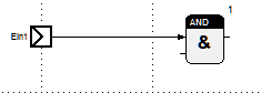
2. Connect the input block with the input of the block
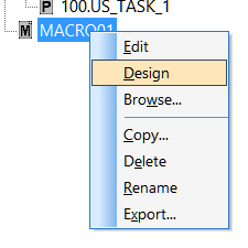
3. Call the structure block design for the macro
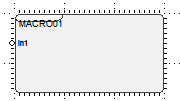
By inserting the input block, a new connector for the macro is generated and listed beside the symbol in the table.
4. Drop the connector on the symbol of the macro
Drag the connector over to the structure block symbol by using of the mouse (refer to the Structure Block Design section).
5. Connect the block output with the input of the macro block
After changing to the worksheet window of the superior structure block with the macro block call and the other block, the new connector can be connected with the output.
3 Mark connections
Procedure
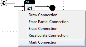
1. Call the context menu for a connection or a connector of a block
By clicking the line segment of a connection or the connector of a block with the right mouse button, the relating context menu is called.
2. Call the Mark Connection command
The connection with all its branches is marked in color to show its path in the worksheet window. This marking remains until the worksheet window is redrawn.
4 Move connections
The horizontal and vertical segments of connections can be arranged with the mouse. Furthermore the connections and attributes (parameter or variables) linked to one connector can be moved to another compatible one.
Procedure (moving from one connector to another one)
1. Grab the end of a connection or a connector attribute
The cursor shape changes to a hand after positioning the mouse on a connected connector. By pressing the left mouse button all linked connections, parameter and variables are grabbed and can be moved until the mouse button is released.
2. Drop at the new connector
The line segment linked to the connector as well as a possibly assigned connector attribute are displayed under the cursor while moving the mouse with the pressed button. After placing the former line end point that is moved with the cursor on a free compatible connector and releasing the mouse button all connection linked to the old connector are deleted and new ones appended to the selected connector are created. The assigned connector attributes are moved similarly. The course of the new connections is calculated using the autorouting.
Before the connections and connector attributes are assigned their compatibility is checked. Error messages will occur when the new connector is occupied or not compatible. In that case all connections and attributes remain linked to the old connector. If the selected connector supports more than one connection then new connections can be assigned even if it is already connected.
By releasing the mouse button over the old connector or outside the area of another connector the operation is canceled.
Procedure (moving line segments)
1. Grab a segment of the connection
When the cursor is moved onto a connecting line, it assumes the shape of two opposite arrows pointing into directions in which movements are possible. The segment can be grabbed by pressing the left mouse button and can be moved in the arrows direction while holding the mouse button down.
2. Drop at the new position
Upon releasing the button, the segment is dropped and the connection is newly drawn. When segments ending in connectors are moved, new segments are generated to preserve the connectors coupling.
When connections are arranged by moving segments, users often do not consider that line paths of a completely different course are calculated if autorouting is activated and blocks are subsequently moved. The arranged segments are preserved when autorouting is deactivated. However, deactivation of autorouting also means that the advantages of autorouting cannot be used.
5 Delete connections
In case of branched connections, the whole line path, or segments thereof, between a connector and a node can be deleted. The whole connection with all its branches can be deleted as follows:
Procedure
1. Call the context menu for a connection or a connector of a block
Upon clicking the line segment of a connection by pressing the right mouse button, the relating context menu is called. For diagonal connections, the context menu of the connector must be opened.
2. Call the Erase Connection command
If more than one input is connected with one output, the segments between the node and the inputs can be deleted.
Procedure
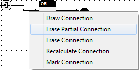
1. Call the context menu for a connection or a connector of a block
When calling the context menu for data flow connections, the cursor must be located on a line between the node and the input. You may also call the context menu of the input.
2. Call the Erase Partial Connection command
6 Orthogonalize connections
This command serves to turn diagonal connections into a right-angled line path.
Procedure
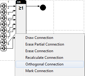
1. Call the context menu for a connector of a block
By clicking a block with the right mouse button, the relating context menu is called. For branched data flow connections, the context menu of the input must be called.
2. Call the Orthogonal Connection command
This command creates a right-angled connection the segments of which can be moved, and facilitates opening of the context menu for connections.