Converter
1 General
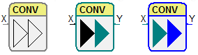
Convert/Assign
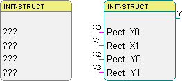
Structure Init
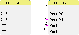
Structure Set
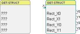
Structure Get
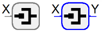
Pin
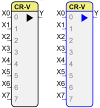
Vector Create
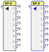
Vector Split
2 User defined data structures
The concept of user defined data structures makes it possible to bundle different or multiple data of a single object. In this way, complex data can be used and displayed more easily. The data structure can be used as a new data type within a program.
The following example shows a data structure called LRECT, which consists of four LONG values. This data structure represents a rectangle defined by two points.
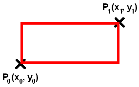
The rectangle forms a logical unit of the four LONG values. Because all four values are needed every time, when dealing with the rectangle, a user defined data structure is the best way to handle it. In doing so, you can handle data efficiently and reduce failures like forgetting one of the values.
To use user defined data structures they have to be defined, created and introduced to the graphical programming system. A step by step tutorial with this example structure can be found here: Create a user defined data structure.
Create a user defined data structure
The following example shows how to create a user defined data structure. We use a structure called “LRECT” containing four LONG values that describe the coordinates of a rectangle. Please pay attention to the correct numeration and the case sensitivity.
Steps:
1. Create the file "PROJEKTNAME“.IADTINI
Use the file "iadvdatatypesbsp.ini“ as a template. This file can be found the "bin" directory. Copy that file to the project folder and rename it. If the file already exists in the project directory go to step 2.
2. Modification of the file „PROJEKTNAME“.IADTINI
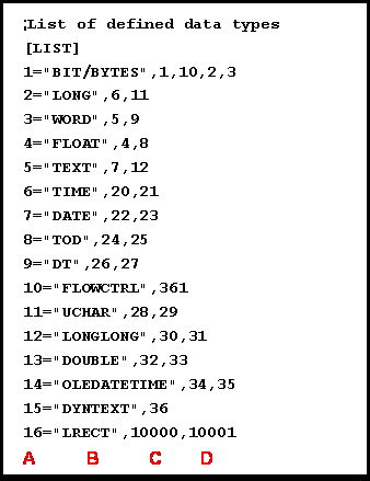
This file contains a list of all used data types. They can be found under "List of defined data types“. A new entry for user defined data structures has to be created here. This will introduce the new data type to the programming system which will be able to provide connectors for this data type. The first value is the counter for the list items (A) followed by the name of the structure (B). The third and fourth entries are IDs for Data data type (C) and Parameter data type (D). They can be chosen freely between 10000 and 32767. Do not use IDs multiple times. The IDs from 0 to 9999 are reserved and must not be used.
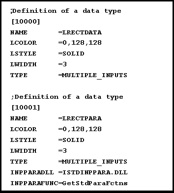
This file also contains additional attribute definitions for the data types, like parameter dialog or the depiction of the connection line. Go to the end of the file and expand the list with new entries like shown in the following figure. First enter the type ID in squared bracket. Remaining attributes are:
| NAME | Internal identifier of the data data type or parameter data type |
| LCOLOR | Line color of the connection; RGB formatted |
| LSTYLE | Line style of the connection (SOLID, DASH, DOT, …) |
| LWIDTH | Width of the connection in pixel |
| TYPE | Number of inputs connected with an output (MULTIPLE_INPUTS vs. SINGLE_INPUT) |
In addition to the parameter data type, the following information have to be entered:
| INPPARADLL | Name of the parameter dialog DLL |
| INPPARAFUNC | Name of the export function for the parameter dialog in the DLL |
3. Create the file "PROJEKTNAME“.STDMEMXML
Use the file "iStdInpPara.xml“ as a template. It can be found in the "bin" directory. Copy that file to the project folder and rename it. If the file already exists in the project directory go to step 4.
4. Modification of the file "PROJEKTNAME“.STDMEMXML
The entries "TypeList" and "MemoryList" of this file have to be extended for the new data structure.
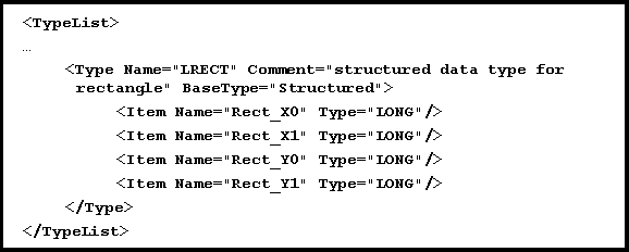
In the list of data types ("TypeList") the new data type has to be entered with its name and additionally with a comment and its base type set to "Strctured". Within this type entry the items of the structure have to be defined with an Item tag. The example includes four LONG values which represents the coordinates of points that define a rectangle.
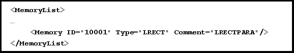
In the memory list (“MemoryList”) the new memory type will be published to the system. The comment contains the name of the parameter data type.
5. Modification of the resource file for the target system
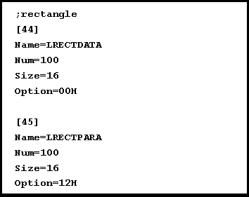
Finally the target systems have to get information about the new data type. The resource allocation file is located in the "Device" directory. In the case of the simulation system it is the file VICK_SIMUL.res. Enter a successive number in the square brackets at the end of the file and input entries according to the following figure.
Name Name of the parameter data type or of the data data type
Num Number of elements allocated for this type
Size Size of memory in bytes needed for one element
Option Characteristics of the memory
The data structure in our example consists of four LONG values so it needs 16 bytes of memory.
The “Option” depends of the target system. The simulation and other implemented systems use the following options that can be combined with OR:
01H Stand data type
02H Parameter memory
04H Bit
08H Copy memory to log file
10H Remanent memory
The data data type has to be defined first.