Speed Meter
The function block transfers the value from the input Value to the assigned Speed Meter HMI object. The value is used in the object to calculate the pointer position.
The object is shown or hidden with the input bShow. And the language of the font and bitmap resources that are used in the speed meter is defined at the input iLang.
HMI object
The HMI Object emulates a circular gauge. The parameter dialog offers a variety of settings to design its scale. The value is displayed by a pointer. Its shape, color and size can also be configured. Alternatively, the calculated scale can be replaced by bitmaps that contain an individual scale with additional markers, texts and frames. At this the later hidden scale must be adapted to the bitmaps to guarantee the correct position of the pointer.
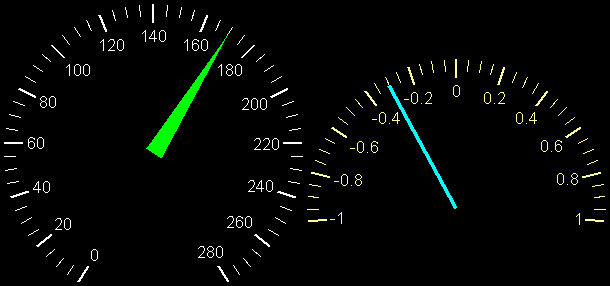
Values below the minimum or above the maximum of the scale are indicated by a different background color and / or another bitmap. In such cases the pointer remains on the minimum or the maximum value.
Parameters
The mask designer is called as the parameter dialog via the context menu of the block. An HMI object of the type "Speed Meter" is assigned to the block by creating or selecting it. With the checkbox in the lower left corner you can switch between global and instanceable assignment.
Default settings for the HMI object are made in the corresponding dialog, which appears after "Additional settings …".
After creating a new Speed Meter HMI object, it is in the automatic mode. That means the size and the position of the scale and the pointer are automatically adjusted in relation to the object. If the calculated scale size is smaller than the width or height of the object, then the scale is centered horizontally or vertically. In difference to the tics the size of the scale values cannot be changed automatically. It is defined by the font that is selected in the parameter dialog.
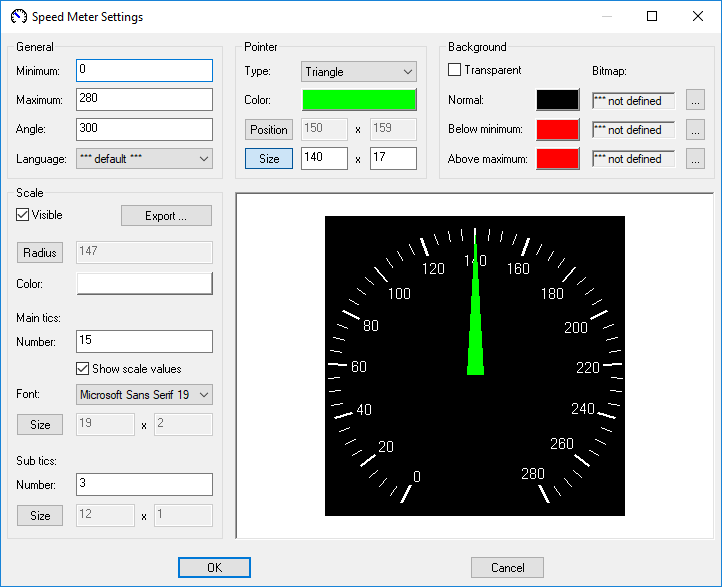
In addition to the minimum and the maximum value the angle of the scale is configured in the section “General” of the parameter dialog. The object supports angles between 190 and 350 degrees. The angle affects the size of the scale and in automatic mode also its position. These and other changes can be observed in the preview window. Large Speed Meter HMI objects can be displayed completely by resizing the parameter dialog.
In the section “Pointer” its shape, color and size are defined as well as the position of its rotation point. There can be chosen between rectangular and triangular pointers. The input fields for the coordinates of the rotation point can be activated and deactivated with the button “Position”. The automatic positioning of the scale and the pointer is simultaneously switched off or on. After the activation of the input fields the remaining automatic size calculations for the scale and the pointer base on the distance between the predetermined rotation point and the object boundaries. At visible scale the size of the pointer is calculated relatively to its radius. If the scale is hidden, then the size bases on the maximum possible scale radius. The button “Size” deactivates the automatic adjustment of the pointers size and activates the input fields for its length and width. By pressing the button again, the size calculation is reactivated and the disabled fields contain the determined values.
In the same manner the automatic calculation of the radius and the tic sizes in the section “Scale” can be deactivated, manually changed and reactivated. The automatic sizes of the tics depend on the scale radius.
Furthermore, the color of the scale, the number of the main und the sub tics as well as the font for the scale values can be configured. If a font with anti-aliasing is used, in addition to the foreground color, several gradations up to the background color of the current state are used to smooth out edges during text output. If the resulting glimmering of the background color interferes when the object is transparent or the scale is written on a bitmap, it is recommended to change the background color or to choose a font without anti-aliasing.
The sub tics are removed by setting their number to 0. Otherwise, up to 99 sub tics are supported between two main tics. At least 2 and at most 99 main tics are drawn. The output of the numbers at the main tics can be prevented by deactivating “Show scale values”. And the checkbox “Visible” is used to hide the entire scale. The former state is restored by marking the checkbox again.
With the button “Export…” a file dialog is opened to save a bitmap with the dimensions of the object that contains the currently configured scale. The bitmap can be edited in external editors, imported as resource and used as a background image. So extra markers, texts and frames can be easily added.
The object is filled with a background color as long as the checkbox “Transparent” is not marked. If the display value is greater than the scale maximum, then the color after “Above maximum” is used. If the value is lower than the minimum, then the object is filled with the color after “Below minimum”. The normal background color appears when the display value is within the configured limits. A resource bitmap can be assigned as background image for each of these states by pressing the corresponding “…” button. If no bitmap has been specified for a state, then no image appears. The images are aligned to the upper left corner of the object and draw even at transparent background.
Bitmap Scale
Shall the calculated scale be replaced by a bitmap, the coordinates of the rotation point as well as the angle and the size of the pointer must be set accordingly. These parameters are known at exported scale bitmaps. Otherwise, the rotation point should be determined first. Subsequently, the calculated scale should be switched visible. And it should be repositioned over the scale in the bitmap by adjusting the angle and the radius. The probably distracting scale values are best disabled. Tics that are extended up to the rotation point are well suited to estimate the angle. If both scales match, then the automatically calculated size of the pointer can be used to derive its final length and width. Finally, the calculated scale is hidden and the minimum and the maximum are entered.
Signals
| Name | I/O | Type(s) | Function |
|---|---|---|---|
| Value | I | FLOAT, DOUBLE, UCHAR, WORD, LONG, LONGLONG | Display value |
| bShow | I | BIT | Show or hide the object |
| iLang | I | WORD | Language resource (ID) |
Note: If inputs are not connected the object appears with the corresponding default parameters. Otherwise the input signals from the function block overwrite the according settings from the parameter dialog.
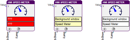
Visualization
The assignment of the HMI object is displayed in the block by the color of the text boxes. A yellowish background indicates a global assignment. If the assignment is instanceable, the background is white. And at missing or incorrect assignment it is red.